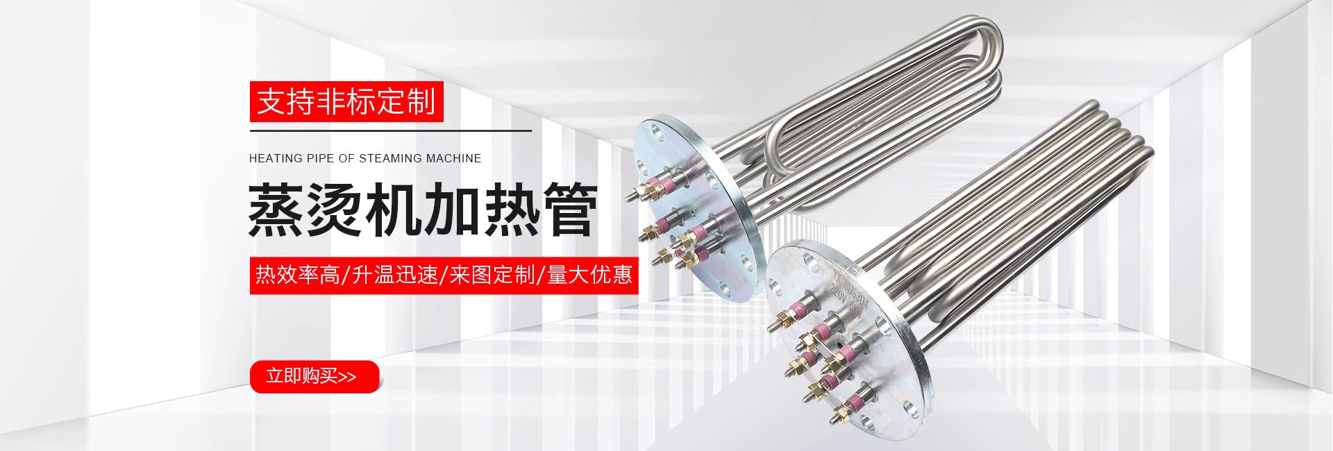
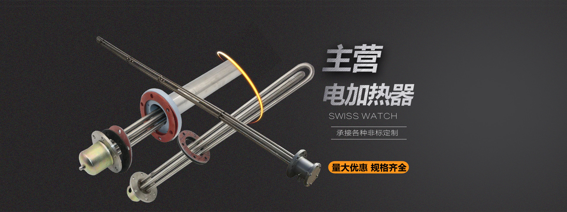

During the design and selection stage, a practical problem is often encountered: for the same air or liquid heating requirement in an explosion-proof area, different solutions show obvious differences in flange specifications, surface load, and wiring methods, and the later installation and maintenance costs also differ accordingly. Structurally, the stainless steel explosion-proof heater consists of electric heating elements, a stainless steel sheath, an explosion-proof junction box, and flange or threaded mounting parts. During selection, the medium type, explosion-proof area classification, installation space, and temperature control requirements must all be taken into consideration, rather than merely comparing power ratings.
According to the operating environment, it can be divided into two categories: air heating and liquid heating. Enclosed air heating and circulating air heating have different requirements for the surface load of the heating tube, and special gas heating also requires consideration of the corrosiveness of the gas composition to the sheath. In liquid heating, the watt density and materials used for heating in water, heating in oil, and heating of acid-base liquids are different and must not be confused. The heating zone of the heating tube should be immersed in the medium to avoid exposure and dry burning. If scaling, thinning, or oil contamination adheres to the sheath surface, the heat transfer conditions will change, so a certain surface load margin should be reserved during selection.
The explosion-proof junction box is usually equipped with an over-temperature control device, which works with an external control system to achieve temperature protection. For high-power applications, flange mounting is mostly used. For example, a 140mm flange electric heater can be used for air duct or tank heating, and the voltage can be designed as 220V or 380V, depending on the on-site power supply and explosion-proof area classification. For air duct installation, brackets are used to secure the heating tube to reduce vibration, and the junction box should be positioned for easy maintenance.
Confirm that the explosion-proof area classification is consistent with the equipment's explosion-proof marking; check the medium name, operating temperature, and flow rate to determine the surface load accordingly; check whether the flange specification, installation depth, and heating zone length match the equipment opening; confirm the power supply voltage, wiring method, and interface form of the over-temperature protection circuit; clarify the compatibility between the sheath material and the medium. After comparing the above items one by one, the differences between solutions can usually be explained, and it is also convenient to standardize spare parts later.